2024
BioImpedance Measurement Device
The goal of the project was to create a small measurement device capable of measuring the ionic concentration of biological samples, with a microfluidic system.The project was part of Marco Carminati's BioChip Course at PoliMi.
The team:
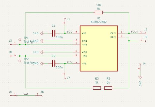
Our design:
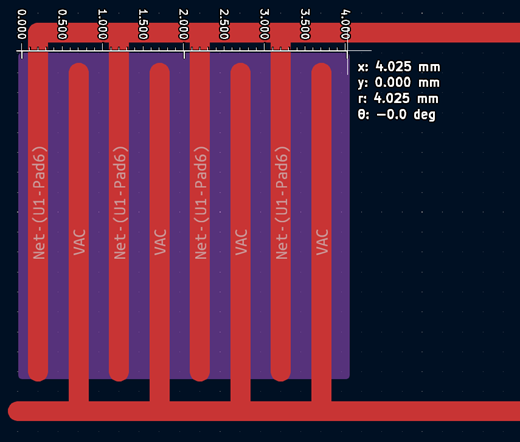
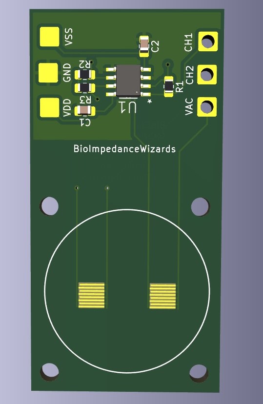
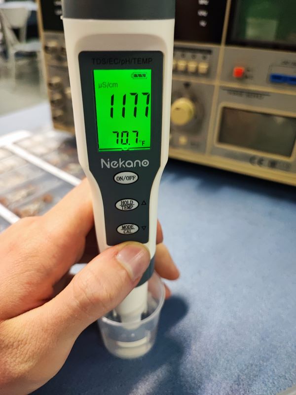
The impedance of the interdigitated electrodes and the solution was calculated based on conformal mapping , and the feedback resistor was sized according to the calculations using Milano's tap water conductivity. We run the calculations for multiple electrode configurations and decided to work with 8 fingers. We decided to have 50% metalization of the gold electrodes (same conductor and gap size) as seen below.
To use both channels of the trans-impedance amplifier we decided to use two electrode pairs and divide the feedback resistor of channel 2 into two parts. This way we could analyze the effect of the different parasitic capacitances.
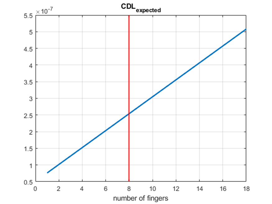
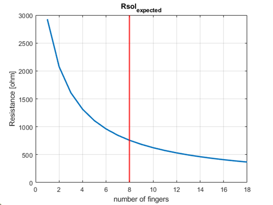
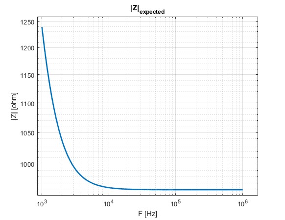
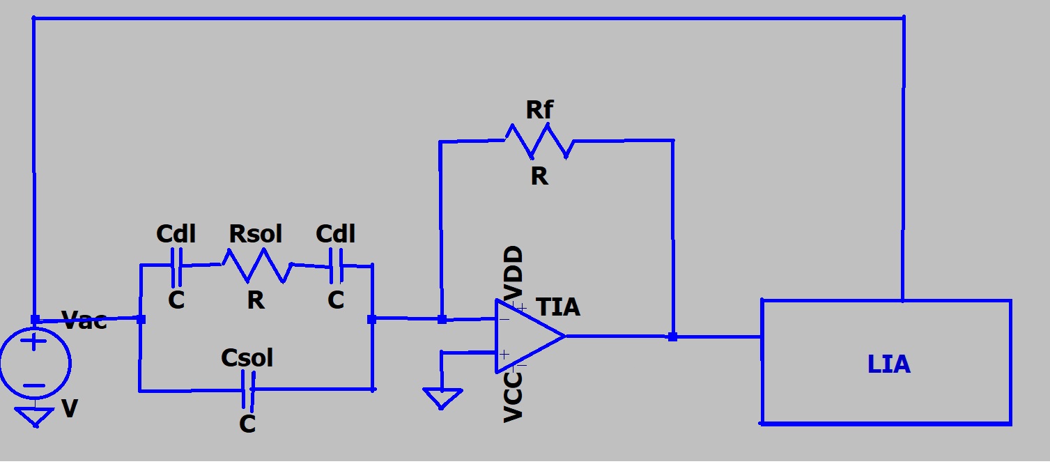
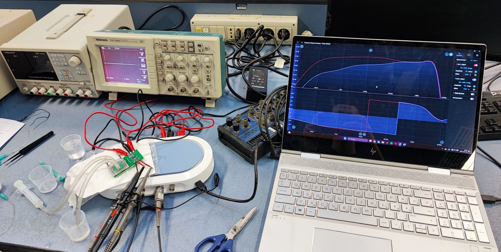
We considered the the impedance of the fluid and the connectors as: $$imp = R_{sol} + \frac{1}{2*π*f*CDL}$$ neglecting the effect of the fluid's capacitance. For the final BandWidth on channel1 is: $$f_{bandwith} = \frac{1}{2*pi*10000*Csf}$$ For channel 2, due to the splitted feedback resistor: $$f_{bandwith} = \frac{1}{2*pi*10000*\frac{Csf}{2}}$$ The resulting bandwiths are over the BandWidth of the Moku measurement device, so during the experiments at some point we added additional external capacitors to decrease the cutoff frequency.
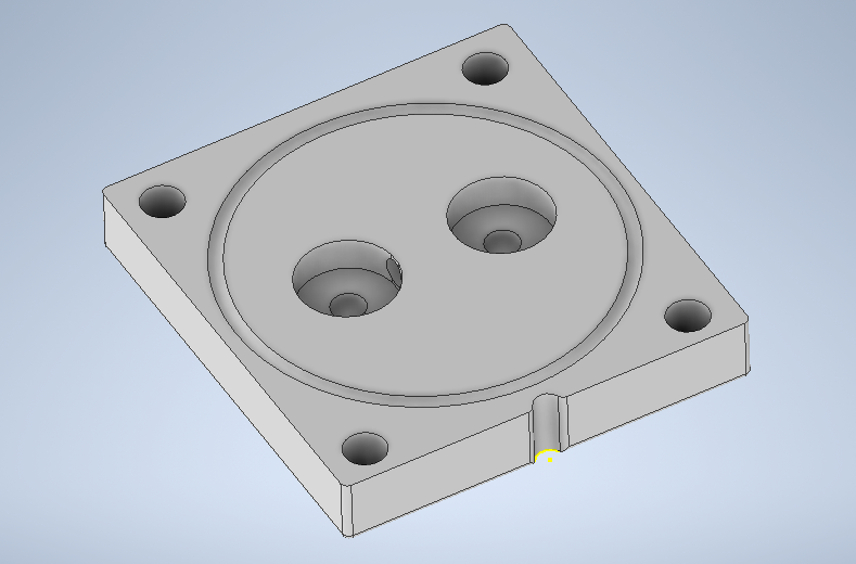
In the microfluidic part we separated the system to 2 main chambers, connected by a small channel, in order to increase the ohmic resistance and reduce the crosstalk between them. The volume of the internal structures can be found in the following table.
| Description | Volume |
|---|---|
| Volume of chambers | 98.2 mm³ |
| Volume of chambers in μl | 98.2 μl |
| Volume of channel | 13.7 mm³ |
| Volume of channel in μl | 13.7 μl |
| Total volume | 210.1 mm³ |
| Total volume in μl | 210.1 μl |

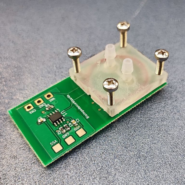
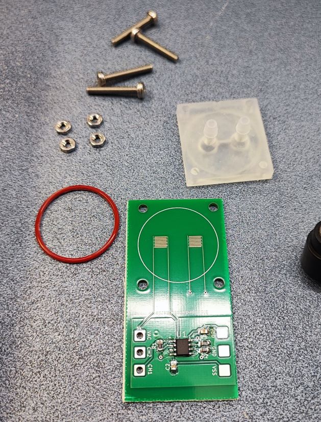
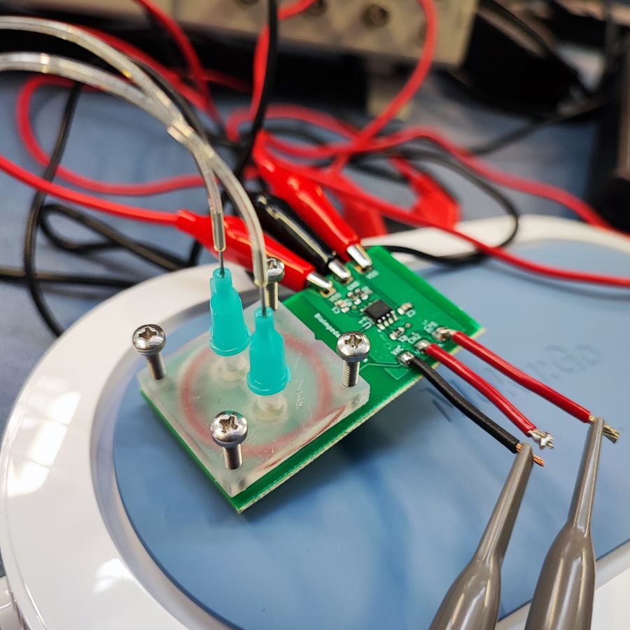
Assembly:
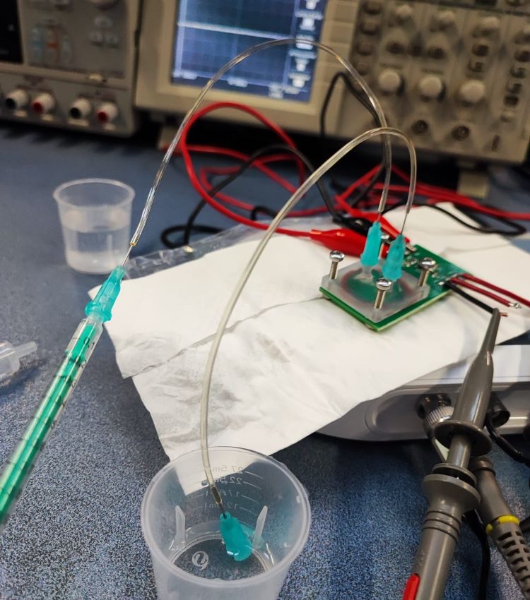
Measurements:
Results:
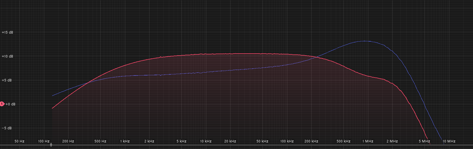
We can conclude that the result of measurements matches the theoretically expected results from the course material. The previous image confirms that splitting the feedback resistor in this design can improve the bandwidth by reducing the parasitic capacitances.
Our class presentation during the design phase: