2021
PID controller test
The goal of the project: Extending my knowledge of PID controllers and trying out their capabilities in real life.
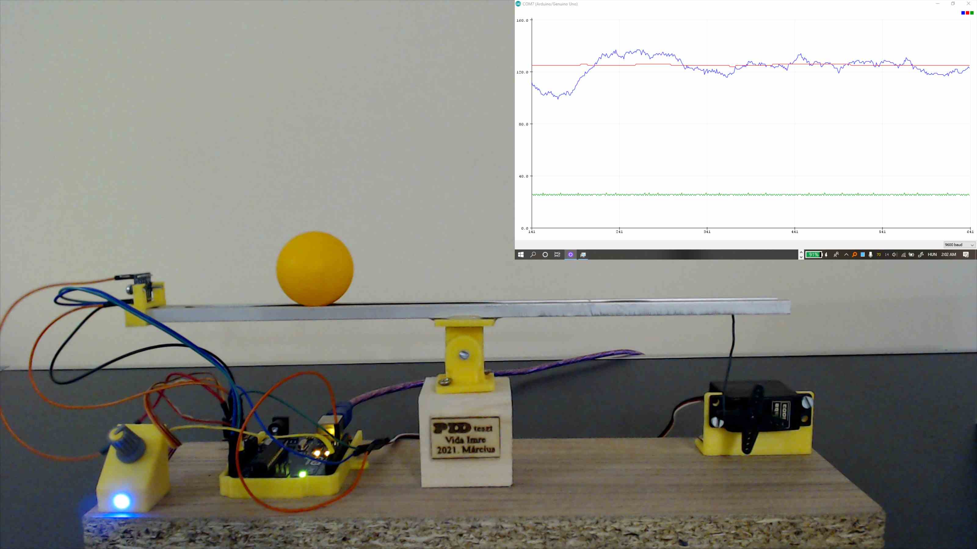
Pictures of the device:

This project is ongoing, errors may be present in the description.
All rights reserved!
Summary:
Hardware:
The project is built on easily accessible components, that are mostly available in every maker's household.
Bill of materials:
- Servo motor
- Arduino Uno
- Laser ToF ranging sensor based on VL53L0X
- 1kΩ linear potentiometer
- LED + 270Ω resistor
- Small-sized MDF board and a wooden cube to raise the moving mechanism a bit.
- A piece of flat aluminium profile, and a ball that rolls well on it. I used a ping-pong ball.
- Some wires, bolts, and basic tools for the assembly
- 3D printed parts ( Stl files are available here. )
- Sensor mount
- Servo mounting frame
- Small hinge
- Mounting plate for the microcontroller
- Control panel
The math behind it:
The controller's goal is to balance and keep the ball in the desired position on top of the aluminium beam. The input of the system, which can be controlled directly, is the angle of the servo. The output is the distance between the sensor and the ball.

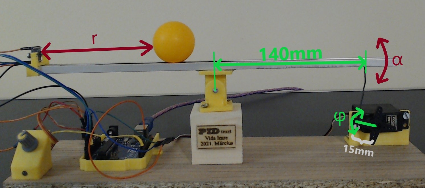
The first step was to declare the variables and enumerate the values used during the calculation. I chose them as the following picture shows:

At first, I calculated, how high can the servo lift one side of the beam by moving ϕ degrees. This equation was calculated concerning the SI system as follows: $$x=\sin \left(φ\right)\cdot \frac{15}{1000}$$ Taking this equation, we can see, that the angle of the beam is dependent on the angle of the servo as follows: $$α=\arcsin \left(\frac{\sin \left(φ\right)\cdot \frac{15}{1000}}{\frac{140}{1000}}\right)$$ This is a nonlinear equation, which could lead to some complex calculations later. Considering the maximum working range of the servo, and plotting this equation using the possible values as an input, it's clearly seen, that this equation has an almost perfect linear equivalent. For the linearization, I used the values at ϕ=±60°degrees. After that, it can be simplified to the form of: m*ϕ Where m is the value of the linear slope.

At this point, the acceleration of the ball can be expressed: $$a=g\cdot \sin \left(α\right)=g\cdot \sin \left(m\cdot \:φ\right)$$ At this point, the acceleration of the ball can be expressed: This is the perfect time to leave the time-domain calculations and start some complex-frequency-domain analysis. Taking the Laplace transformed form of the acceleration, multiplied two times by (1/s) we get to the Laplace transformed form of the movement, which is the second integral of the acceleration.
Now the transfer function can be expressed as follows: $$Wsystem(s)=\frac{7.875e17 s^2}{4.504e17 s^4 + 1.431e16 s^2}$$ This is a continuous-time transfer function, but since this is going to be used for a sampled, measurement-based system, dealing with the dead-time between measurements is mandatory. This dead-time will decrease the Phase-Margin of the controller significantly. I chose the maximum dead-time to 27ms in this case, knowing the maximum time of the laser distance measurement and the following calculations and communication can be done in this amount of time, even in the worst-case scenario.
The new, updated transfer function is the following: $$Wsystem(s)=e^{-0.027\cdot \:s}\cdot \frac{7.875e17s^2}{4.504e17s^4+1.431e16s^2}$$ The main point is to keep the ball in the desired position, by controlling it through the servo motor. The control system has been chosen to be a PID controller. The control loop can be assumed as follows, without considering the noises and other disturbances from the environment.

The general equation of a PID controller: $$u\left(t\right)=K_p\cdot e\left(t\right)+Ki\cdot \int _0^te\left(t'\right)dt'\:+\:K_d\cdot \frac{de\left(t\right)}{dt}\:$$ Where Ki, Kd, and Kp are tuneable constants.
The Bode graph of the open-loop can be drawn as follows, considering t design rule of 60° degrees Phase-Margin. This Phase margin guarantees, that the unconsidered signal noises and external disturbances won't make the ball unstable.

The controller's parameters that fulfill my design requirements are:
- Kp = 0.3949
- Ki = 0.0082
- Kd = 10.8231
Final results:
Further analysis:
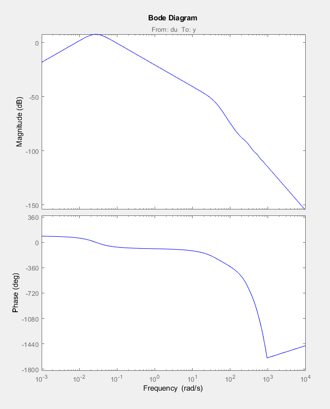
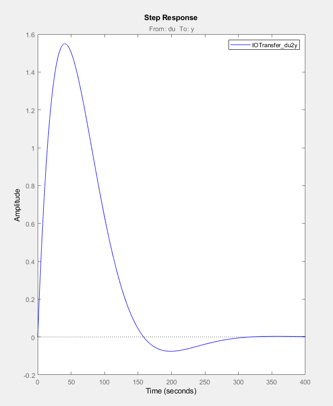
Although the PID controller used provides adequate setpoint tracking, and due to the integrator with zero remaining error, its interference suppression is really slow. This is due to the fact that the goal was to optimize the speed between the input and output of the system, in return, the interference suppression's transient from the input to the output slowed down significantly. In this case, such a disturbance could be modeled by lifting one side of the device by its base and placing it at a higher point.
The interference suppression's transient of the current setup can be seen on the following
images:


The solution for this can be a controller with 2 degrees of freedom. More details are coming soon.
Competitions and achievements:
- More details are coming soon.